Edge Controller
2 min read
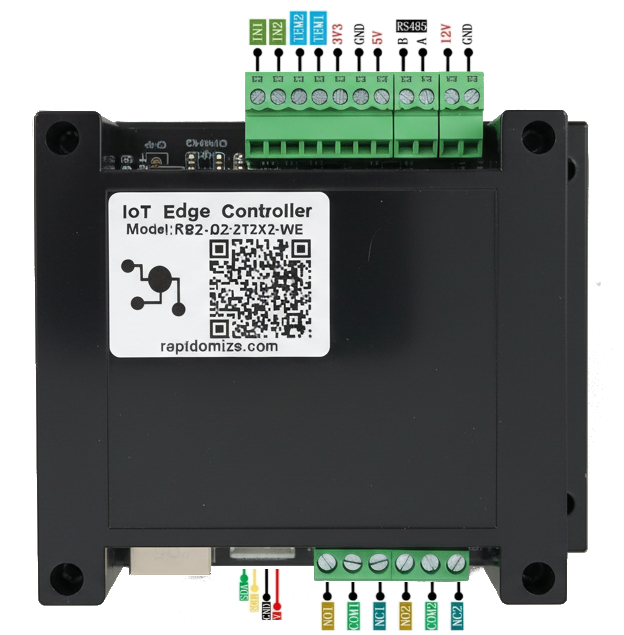
Rapidomize IoT Edge Controller
Model: rpz-d2x2t2ux-we
- Build your own IoT controller solutions using this ESP32 or STM32 based controller
- Comes with various connectivity options & interfacing capability.
- Digital & Analog I/Os, RS485, IIC, SPI, WiFi, BLE
- Pluggable GSM modules
- Extensible IO modules allow IO expansion up to 32 IO ports and with IIC up to 127 & RS485 up to 256 devices

- WIFI, Ethernet, and Bluetooth connectivity
- Digital Input x 2
- IN1 — GPIO36
- IN2 — GPIO39
- If INx short connect to GND, the GPIO will detect LOW signal;
- Digital Out (Relay) x 2
- Relay 01 — GPIO2
- Relay 02 — GPI015
- Rating: 10A/277VAC, 12A/125VAC
- Relay parameters: JQC-3FF-5VDC-1ZS
- RS485 Port
- A — GPIO35
- B — GPIO32
- Temperature detection x 2 (1 wire) using DS18B20
- TEM1 — GPIO33
- TEM2 — GPIO14
- By simply connecting 3V3, GND, and either T1 or T2, temperature detection can be achieved.
- Buzzer
- GPIO12
- used for system startup prompts, connection success prompts, abnormal alarm, development and debugging assistance, and operation confirmation.
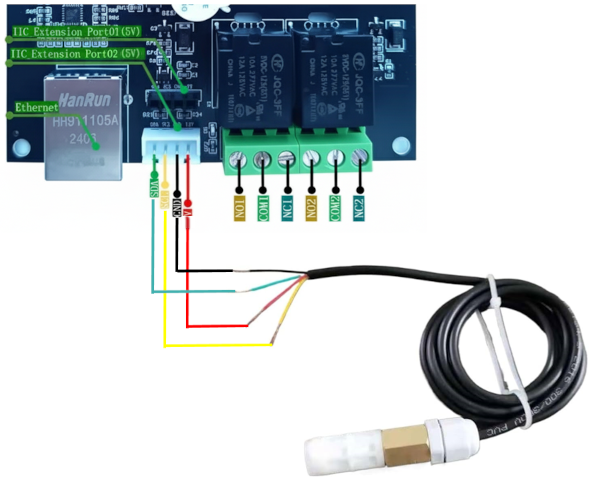
- IIC expansion interface * 2
- SDA — GPIO4, SCL — GPIO16
- Port 1 (12V): the above pins, can be connected to DO8 to achieve the interface expansion of the relay output.
- Port 2 (5V): same pins, using this port the EA2 and SHTX sensors can be connected to achieve temperature and humidity detection.
- Supports SIM7600 4G module and SIM800L 2G module
- GSM_RX - GPIO13, GSM_TX - GPIO5
- SIM7600 4G_Module: the above pins, used for remote communication and remote control
- SIM800L 2G_Module: same pins, used for remote communication, remote control, SMS notifications and simple IoT applications.
- Ethernet Port
- used for high speed and stable network connection, remote access and control, and interconnection with other network devices.
Connectivity
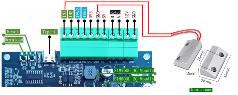
Digital input connection
The following is the wiring method, connected to a wired door sensor with NO and NC states and a 2-gang self-reset Switch. IN1 should be connected to Door sensor’s NO line. IN2 should be connected to Door sensor’s NC line.
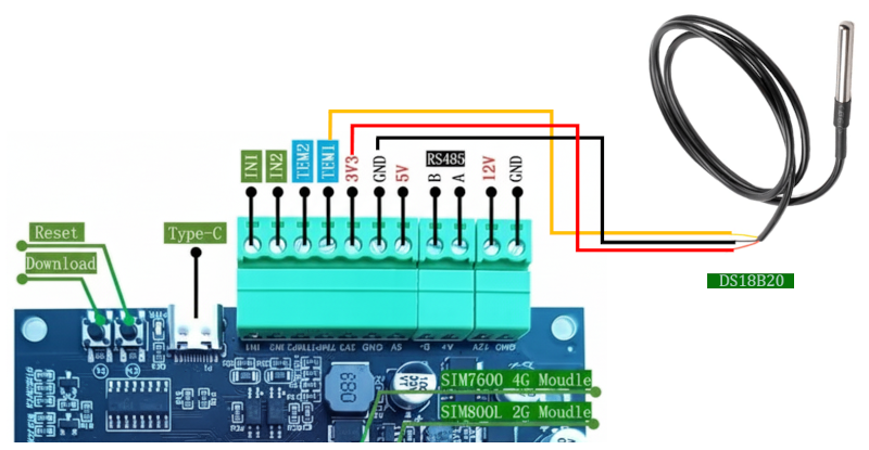
DS18B20 temperature sensor connection
GND should be connected to DS18B20 sensor’s GND line. 3V3 should be connected to DS18B20 sensor’s VDD line. TEM1 should be connected to DS18B20 sensor’s DQ line.
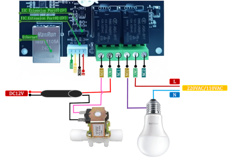
Relay output connection
The following is the wiring method, connected to a 12Vdc solonoid valve and a 220Vac LED light.
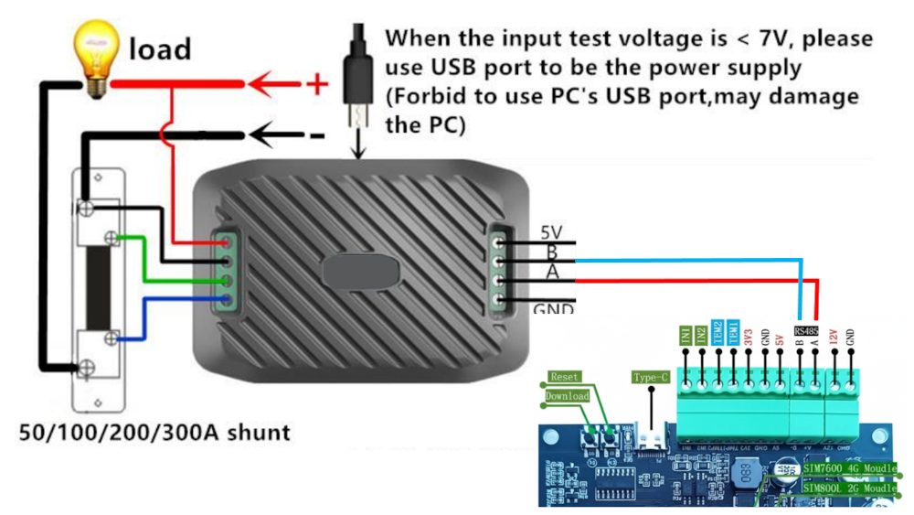
RS485 connection to Power meter
The RS485 communication interfaces can be connected to RS485 devices or devices with ModBus communication, etc.
IIC GPIO expansion
SDK and Code Examples
See here for SDK and Code Example